

Antecedentes
Los requerimientos de espacio son componentes importantes de estandarización ya que sirven para garantizar la accesibilidad para las personas que utilizan dispositivos de movilidad, tales como scooters y sillas de ruedas (Steinfeld et al., 2010) . Por lo tanto, es importante tener en cuenta las dimensiones, la masa y el espacio necesarios en el diseño de sillas de ruedas, así como en el diseño universal. Estos factores pueden determinar cómo el usuario puede usar el dispositivo de movilidad y si éste cabe en su entorno, hogar, lugar de trabajo y vehículo (Rentschler, 2002). Además, el peso de una silla de ruedas también puede afectar su transporte y puede requerir el uso de dispositivos adicionales, como una rampa o un elevador.
Propósito
Determinar de manera consistente la masa, longitud, ancho, altura y radio de giro de la silla de ruedas.
Aparato
Plano de prueba plano, barreras verticales ajustables (por ejemplo, paredes de madera portátiles) y herramientas de medición, como una cinta métrica y un ángulo recto.
Configuración de prueba
La silla de ruedas de prueba debe configurarse según las recomendaciones del fabricante, puede incluir dispositivos antivuelco. Coloque los dispositivos antivuelco en la posición que se pueda colocar lo más atrás posible sin afectar la configuración de la silla de ruedas.
Si va a probar una silla de ruedas que tiene baterías, asegúrese de que las baterías estén completamente cargadas antes de continuar con la prueba. Además, siga las recomendaciones del fabricante sobre la velocidad, si esto no se menciona, use la velocidad máxima.
Método de prueba
- Coloque la silla de ruedas en el lugar de prueba.
- Prepare la silla de ruedas para su propulsión de acuerdo con las recomendaciones del fabricante.
- Asegúrese de que las ruedas traseras y ruedas orientables delanteras estén direccionadas hacia adelante, en otras palabras, deben estar orientadas como si la propulsión de la silla de ruedas fuera hacia adelante.
Mediciones
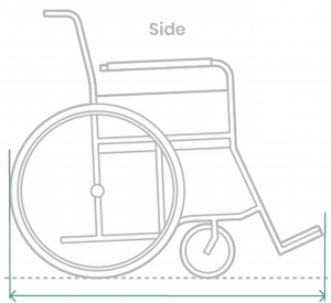
Longitud total
También conocida como profundidad total de la silla de ruedas, es la distancia entre los puntos de más hacia adelante y más hacia atrás de la silla de ruedas. Al medir la longitud de la silla de ruedas, debe incluir todos los componentes para su uso, como soportes para piernas, apoyapiés y dispositivos antivuelco ( Waugh et al., 2013) . Las ruedas deben estar orientadas de tal manera que la propulsión de la silla de ruedas sea en dirección hacia adelante. (ISO, 2008) .
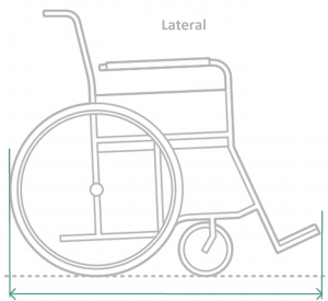
Figura modificada de (Maddock, 2020)
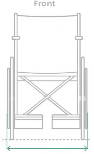
Ancho total
Mida la distancia entre los puntos laterales más sobresalientes de la silla de ruedas. En algunos casos, los puntos laterales más sobresalientes podrían ser los aros propulsores, apoyabrazos, etc. Al medir el ancho de la silla de ruedas, debe incluir todos los componentes para su uso, como apoyapiés y soportes de piernas, dispositivos antivuelcos. Las ruedas orientables deben estar en dirección hacia adelante (Waugh et al., 2013).
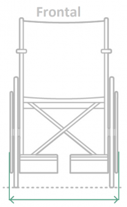
Figura modificada de (Maddock, 2020)
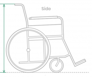
Altura de los manubrios
Primero, identifique el punto medio del lado del manubrio. Luego, mida la distancia entre este punto y el piso (plano de prueba) (Waugh et al., 2013) .
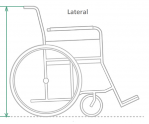
Figura modificada de (Maddock, 2020)
Masa total
Prepare la silla de ruedas de manera que ésta incluya todos los componentes para su uso, como soportes para piernas, apoyapiés, dispositivos antivuelco. Pese la silla de ruedas desocupada (Waugh et al., 2013) .
Distancia al piso
Mida la distancia entre cualquier componente de la silla de ruedas (que no sea una rueda trasera o rueda orientable) que esté más cerca del suelo y el suelo (Waugh et al., 2013). En algunos casos, la distancia al suelo se mediría entre el apoyaapiés fijo y el suelo. Cuando hay reposapiés ajustables, la distancia al suelo debe medirse entre el componente más cercano al suelo.
![]()
Figura modificada de ISO 7176-5 (2008) .
Para las siguientes medidas, pliegue la silla de ruedas, en caso de ser posible, o desmóntela para transportarla o como si la estuviera guardando. En otras palabras, puede que sea posible que deba quitar las ruedas traseras y los soportes para las piernas o los apoyapiés.
Longitud de almacenamiento (profundidad)
Una vez que se hayan removido estos componentes, mida la distancia entre los puntos de más adelante y más atrás de la silla de ruedas cuando esté plegada (Waugh et al., 2013) .
Ancho de almacenamiento
Una vez que se hayan retirado los componentes y se haya plegado la silla de ruedas, mida la distancia mínima entre los puntos laterales más sobresalientes de la silla de ruedas (Waugh et al., 2013) .
Altura de almacenamiento
Una vez que se hayan quitado los componentes y se haya plegado la silla de ruedas, mida la distancia entre el punto más alto de la silla de ruedas cuando esté plegada y el piso (plano de prueba) (Waugh et al., 2013) .
Masa de la parte más pesada
Una vez que se hayan retirado los componentes y se haya desmontado la silla de ruedas , pese la parte más pesada de la silla de ruedas (Waugh et al., 2013) .
Las siguientes medidas pueden requerir que use las barreras o paredes ajustables:
Diámetro de giro
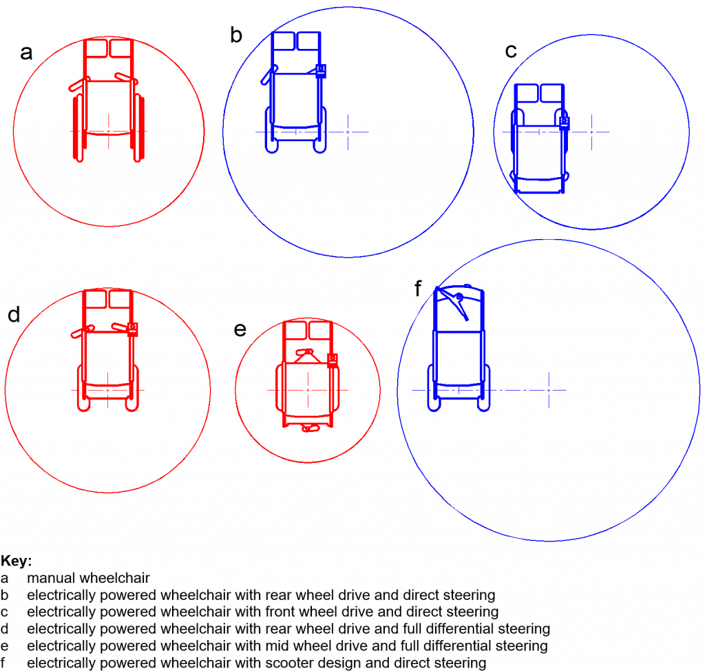
Esta medida también se conoce como radio de giro o círculo de giro. Es el círculo más pequeño en el que se puede conducir la silla de ruedas haciendo un giro de 360 ° (Waugh et al., 2013) .
La siguiente figura muestra ejemplos de diámetros de giro para diferentes tipos de sillas de ruedas. Para obtener detalles sobre el cálculo de las sillas de ruedas con dirección directa y dirección diferencial, revise la sección 5- Diámetro de giro en “ Área de trabajo de sillas de ruedas” (documento en inglés) de Wien & Ziegler (2003)
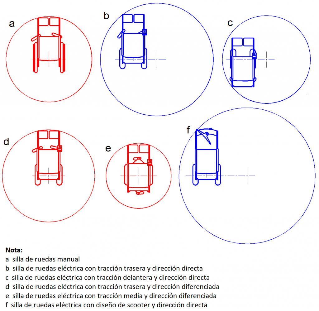
Figura adaptada de Wien y Ziegler (2003 ) .
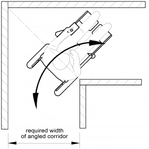
Ancho requerido de un corredor
Use las paredes ajustables para crear un corredor de 90°, como se muestra en la figura a continuación.
Una silla de ruedas ocupada debe ser conducido en este corredor hacia adelante y hacia atrás sin tener en contacto con las paredes. Mida el ancho mínimo del corredor en el que la silla de ruedas ocupada puede hacer esto (Wien y Ziegler, 2003) .
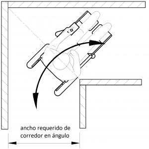
Figura adaptada de Wien y Ziegler (2003 ) .
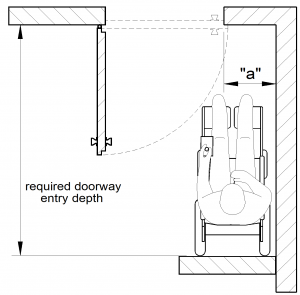
Profundidad requerida de entrada de un corredor
Consulte la figura a continuación para garantizar la colocación de la silla de ruedas en relación con la puerta antes de tomar medidas.
La silla de ruedas puede necesitar retroceder para dar espacio a la puerta batiente. Puede utilizar la pared ajustable en un lado de la silla de ruedas para cambiar la medición “a” y la otra pared ajustable detrás de la silla de ruedas, este último dará la medida de de la profundidad mínima requerida para la entrada de un corredor con puerta abatible. La medida “a” estará determinada por el tamaño general de la silla de ruedas (Wien y Ziegler, 2003) .
Para obtener más detalles sobre los límites típicos y recomendados de la profundidad de entrada de puerta requerida, consulte la sección 9 – Profundidad de entrada de puerta requerida en ” Área de trabajo de sillas de ruedas” (documento en inglés) por Wien & Ziegler (2003).
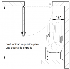
Figura modificada de Wien y Ziegler (2003 )
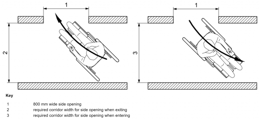
Ancho de pasillo requerido para salida lateral
Use las paredes ajustables para construir un espacio en forma de T. Esta medida corresponde a la distancia mínima en la que la silla de ruedas puede entrar y salir del corredor en forma de T (ISO, 2008) .
La siguiente figura muestra cómo se debe conducir la silla de ruedas para esta medición. En caso de que las medidas 2 y 3 sean diferentes, reporte la medida en la que la silla de ruedas puede entrar y salir con éxito del corredor.
Para obtener más detalles sobre los límites típicos y recomendados del ancho de pasillo requerido para la salida lateral, consulte la sección 10 – Ancho de pasillo requerido para la salida lateral en ” Área de trabajo de sillas de ruedas” (documento en inglés) por Wien y Ziegler (2003)
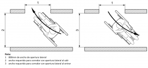
Figura modificada de ISO (2008)
Referencias
ISO. (2008). ISO 7176-5:2008(en) Wheelchairs—Part 5: Determination of dimensions, mass and manoeuvring space. https://www.iso.org/obp/ui/#iso:std:iso:7176:-5:ed-2:v1:en
Maddock, B. (2020, April 8). Wheelchairs. Dimensions.Guide. https://www.dimensions.guide/element/wheelchairs
Rentschler, A. (2002). Analysis of the ANSI/RESNA Wheelchair Standards: A Comparison Study of Five Different Types of Electric Powered Wheelchairs. University of Pittsburgh (Unpublished).
Steinfeld, E., Maisel, J., Feathers, D., & D’Souza, C. (2010). Anthropometry and standards for wheeled mobility: An international comparison. 22(1), 51–67. https://doi.org/10.1080/10400430903520280
Waugh, K., Crane, B., Taylor, S., Davis, K., Cwertnia, S., Brown, L., Saftler, F., & Christie, S. (2013). Glossary of Wheelchair Terms and Definitions. University of Colorado, Assistive Technology Partners, through a grant from the Paralyzed Veterans Association.
Wien, F. I. O. T., & Ziegler, J. (2003). Working area of wheelchairs. Space requirements of wheeled mobility: An international workshop, IDEA Center, Univeristy at Buffalo, NY, USA. http://www.udeworld.com/documents/anthropometry/Space%20Workshop/Papers/WEB%20-%20Working%20Area%20of%20%20Wheelchairs%20(Ziegler).doc